

 Blog
Modern commercial buildings require air-conditioning systems that provide reliable cooling, flexible temperature control, and efficient operation. One technology widely used in commercial HVAC applications is the Variable Refrigerant Flow (VRF) system, also known as Variable Refrigerant Volume (VRV).
VRF and VRV systems are designed to provide cooling and, in compatible configurations, heating to multiple indoor units connected to an outdoor unit or group of outdoor units. They allow different areas of a building to have individual temperature controls, making them suitable for offices, hotels, retail properties, restaurants, and other commercial environments.
However, achieving reliable performance requires more than selecting the right equipment. Proper system design, refrigerant piping, electrical installation, commissioning, and regular maintenance are all important.
For building owners and facility managers, understanding these systems can help with equipment selection, contractor evaluation, maintenance planning, and long-term HVAC management.
This guide explains how VRF and VRV systems work, their main components, installation stages, commissioning requirements, preventive maintenance procedures, common problems, and the importance of professional HVAC support.
What Are VRF and VRV Systems?
VRF stands for Variable Refrigerant Flow, while VRV stands for Variable Refrigerant Volume. Both terms describe air-conditioning technologies that regulate refrigerant flow according to the cooling or heating requirements of different indoor spaces.
VRV is Daikin’s branded terminology for its variable refrigerant volume technology, while VRF is the commonly used general industry term.
These systems connect multiple indoor units to an outdoor unit or system arrangement. The equipment adjusts its operation according to demand, allowing different zones to receive the required cooling or heating.
Depending on the model and configuration, VRF/VRV systems may support:
- Multiple indoor units.
- Individual zone temperature control.
- Variable-capacity operation.
- Cooling-only or heat-pump operation.
- Simultaneous heating and cooling in compatible heat-recovery systems.
- Centralised or individual control options.
The exact features depend on the manufacturer, equipment model, and system configuration.
How Do VRF and VRV Systems Work?
VRF and VRV systems operate by controlling the flow of refrigerant through a connected network of indoor and outdoor equipment.
The outdoor unit adjusts compressor operation according to the system’s cooling or heating demand. Refrigerant circulates through the connected piping and indoor units, where heat is transferred between the refrigerant and the indoor air.
Each indoor unit serves a specific room or zone. Depending on the system design, occupants can adjust the temperature of individual areas through local or central controls.
Basic Operating Process
- The indoor unit detects the room temperature and control demand.
- The system communicates the required cooling or heating capacity.
- The outdoor unit adjusts compressor operation as needed.
- Refrigerant flows through the designed piping network.
- Indoor units transfer heat between the refrigerant and room air.
- The system continuously adjusts operation according to demand and operating conditions.
In a heat-pump system, the system generally operates in one mode at a time across its connected arrangement, subject to the manufacturer’s design. Heat-recovery configurations can support simultaneous heating and cooling in different zones when the system is specifically designed for that purpose.
Main Components of a VRF/VRV System
Understanding the main components helps building owners and facility managers understand installation and maintenance requirements.
1. Outdoor Unit
The outdoor unit contains major components responsible for refrigerant circulation and heat exchange.
Depending on the model, it may include:
- Compressor.
- Condenser or heat exchanger.
- Outdoor fan.
- Electronic control components.
- Refrigerant management components.
- Sensors and protective devices.
The outdoor unit’s capacity and configuration should be selected according to the calculated building requirements and manufacturer design limitations.
2. Indoor Units
Indoor units are installed in individual rooms or zones to provide cooling or heating.
Common indoor unit types include:
- Wall-mounted units.
- Ceiling cassette units.
- Concealed ducted units.
- Ceiling-suspended units.
- Floor-standing units.
The selection depends on room layout, ceiling arrangement, airflow requirements, appearance, and the intended use of the space.
3. Refrigerant Piping
Refrigerant piping connects the outdoor and indoor units and allows refrigerant to circulate through the system.
The piping arrangement must follow the manufacturer’s engineering requirements.
Important considerations include:
- Correct pipe diameter.
- Permitted piping length.
- Height differences.
- Branch connection arrangements.
- Joint and connection quality.
- Pipe insulation.
- Support and protection.
- Refrigerant charge calculations.
Incorrect piping design or installation can affect system performance and reliability.
4. Branch Joints and Branch Selector Units
Depending on the system configuration, branch joints or selector units distribute refrigerant to connected indoor units.
In compatible heat-recovery systems, branch selector equipment supports the distribution required for different zones to operate in heating or cooling modes.
These components must be selected and installed according to the manufacturer’s approved system design.
5. Control System
The control system manages indoor and outdoor unit operation.
Depending on the equipment, control options may include:
- Individual room controllers.
- Centralised controllers.
- Touchscreen control panels.
- Building Management System (BMS) integration.
- Scheduling and operating controls.
A correctly configured control system helps coordinate indoor units and provides facility teams with better operational visibility.
6. Condensate Drainage
Indoor units produce condensate during cooling operation. Drainage arrangements remove this water from the equipment.
The drainage system should be installed with suitable routing, slope, connections, and support according to the manufacturer’s instructions.
Drainage problems can lead to water leakage and damage to ceilings, walls, or nearby equipment.
Types of VRF and VRV Systems
VRF and VRV systems are available in different configurations depending on building requirements.
1. Heat Pump VRF Systems
Heat-pump VRF systems generally provide either cooling or heating through the connected system arrangement.
They are commonly considered for buildings where multiple indoor units require coordinated operation.
Potential applications include:
- Commercial offices.
- Retail properties.
- Hotels with suitable operating arrangements.
- Educational facilities.
- Multi-zone commercial spaces.
2. Heat Recovery VRF Systems
Heat-recovery systems are designed to support simultaneous heating and cooling in different zones, depending on the equipment configuration.
For example, a building may have one area requiring cooling while another requires heating. A compatible heat-recovery system can transfer and manage heat according to the system design.
These systems may be useful in buildings with different room orientations, occupancy patterns, or internal heat loads.
3. Air-Cooled VRF Systems
Air-cooled systems exchange heat with outdoor air through the outdoor unit.
They are commonly considered for commercial buildings where suitable outdoor installation locations and airflow clearances are available.
4. Water-Cooled VRF Systems
Water-cooled VRF systems use a water circuit for heat exchange rather than relying solely on outdoor air at the unit.
Their suitability depends on the building’s water infrastructure, equipment design, installation conditions, and maintenance requirements.
Benefits of VRF and VRV Systems for Commercial Buildings
VRF and VRV systems offer several features that may make them suitable for commercial properties.
1. Individual Zone Temperature Control
One of the main benefits is the ability to control different indoor areas separately.
For example, offices, meeting rooms, reception areas, and other zones can have different temperature requirements.
This can improve occupant comfort when the system is properly designed and operated.
2. Flexible Indoor Unit Selection
Different indoor unit styles can be selected according to the room layout and architectural requirements.
Ceiling cassette units, ducted units, wall-mounted units, and other compatible options provide flexibility for different commercial environments.
3. Variable-Capacity Operation
VRF/VRV technology adjusts system operation according to demand.
Rather than operating continuously at one fixed capacity, compatible systems can vary compressor output to match changing cooling or heating requirements.
Actual energy performance depends on system design, equipment selection, controls, climate, and operating conditions.
4. Suitable for Multiple Commercial Zones
A VRF/VRV arrangement can serve several rooms or areas through a connected system.
This can be useful in buildings where different spaces have separate temperature requirements.
5. Flexible Design Options
VRF/VRV systems can support a range of building layouts, indoor unit combinations, and control arrangements.
However, piping limits, capacity requirements, outdoor unit location, and manufacturer restrictions must be considered during design.
6. Centralised Control Options
Some systems can be integrated with centralised control platforms or building management systems.
This may help facility teams manage operating schedules, monitor system status, and coordinate building HVAC operation.
VRF and VRV System Applications
These systems are used in a range of commercial and institutional environments.
Building type | Typical application |
Corporate offices | Individual cooling control for work areas and meeting rooms |
Hotels | Temperature control for guest rooms and selected shared areas |
Retail stores | Cooling for sales floors, display areas, and offices |
Restaurants | Cooling for dining areas and other suitable zones |
Educational buildings | Separate temperature control for classrooms and offices |
Commercial complexes | Multi-zone air-conditioning arrangements |
Healthcare facilities | Suitable HVAC zones where system design meets project requirements |
Residential developments | Individual temperature control for selected apartments or villas |
For specialist environments such as healthcare, laboratories, or controlled facilities, VRF/VRV suitability must be assessed against the required ventilation, filtration, pressure, humidity, and other environmental specifications. A VRF system alone does not establish compliance with specialist indoor-environment requirements.
VRF and VRV System Installation: Step-by-Step Guide
Correct installation is essential for system performance, safety, and equipment reliability.
VRF/VRV installation should be carried out by appropriately trained and authorised HVAC professionals following the specific manufacturer’s installation and engineering documentation.
Step 1: Site Assessment
The installation process begins with reviewing the building and identifying its cooling and heating requirements.
The assessment may consider:
- Building layout.
- Room dimensions.
- Ceiling heights.
- Window positions.
- Occupancy levels.
- Internal heat loads.
- Lighting and equipment loads.
- Outdoor installation locations.
- Available electrical supply.
- Existing HVAC infrastructure.
- Refrigerant piping routes.
A site assessment helps identify practical installation limitations before equipment is selected.
Step 2: Cooling Load Calculation and System Design
The system should be designed according to the calculated cooling and heating requirements of the building.
Design considerations include:
- Room-by-room load calculations.
- Indoor unit capacity.
- Outdoor unit capacity.
- Connected capacity requirements.
- Diversity and simultaneous demand.
- Indoor unit combinations.
- Refrigerant piping design.
- Permitted piping lengths.
- Height differences.
- Outdoor unit clearances.
- Electrical requirements.
- Control arrangements.
Equipment selection should not rely only on floor area. A proper load calculation and manufacturer-approved design are important.
Step 3: Indoor and Outdoor Unit Selection
Once the system requirements are understood, suitable equipment can be selected.
Indoor unit selection should consider:
- Room size and cooling requirements.
- Ceiling type and available installation space.
- Air distribution.
- Noise considerations.
- Maintenance access.
- Architectural appearance.
Outdoor unit selection should consider capacity, installation location, airflow, access for maintenance, and manufacturer requirements.
Step 4: Outdoor Unit Installation
Outdoor units should be installed in locations that meet the manufacturer’s requirements.
Important considerations include:
- Stable supporting foundations or mounting arrangements.
- Suitable airflow clearance.
- Access for maintenance.
- Protection from inappropriate environmental exposure.
- Drainage and condensate considerations where relevant.
- Vibration and noise considerations.
- Electrical isolation and connection requirements.
Outdoor equipment should not be installed in a restricted location that prevents proper airflow or future servicing.
Step 5: Indoor Unit Installation
Indoor units should be positioned according to the approved design and manufacturer’s instructions.
Installation considerations include:
- Correct mounting support.
- Suitable air discharge direction.
- Access to filters and service panels.
- Drainage connections.
- Refrigerant pipe connections.
- Electrical and communication wiring.
- Ceiling coordination.
- Adequate space for maintenance.
Incorrect indoor unit positioning can create airflow problems, uneven temperatures, or maintenance difficulties.
Step 6: Refrigerant Piping Installation
Refrigerant piping is one of the most important parts of a VRF/VRV installation.
The piping network must follow the approved design and equipment specifications.
Installation considerations include:
- Correct pipe material and dimensions.
- Approved branch joints.
- Correct pipe routing.
- Suitable supports.
- Proper insulation.
- Protection against contamination.
- Correct jointing procedures.
- Compliance with manufacturer limits.
Piping work must be performed by trained personnel using appropriate tools and procedures.
Step 7: Refrigerant Piping Testing and Evacuation
Before the system is commissioned, the refrigerant piping must undergo the testing and preparation procedures specified by the manufacturer.
These may include:
- Pressure testing using the specified method and approved test medium.
- Leak inspection.
- Correct isolation of test sections.
- Evacuation using suitable vacuum equipment.
- Verification of the required evacuation conditions.
- Documentation of the results.
Test pressures, holding periods, evacuation targets, and procedures are model-specific. They must be taken from the applicable manufacturer documentation rather than assumed from a generic checklist.
Never use oxygen or compressed air containing oxygen for refrigerant-system pressure testing.
Step 8: Electrical and Communication Connections
Electrical and communication wiring should be installed according to the equipment specifications and approved electrical design.
Checks may include:
- Power supply suitability.
- Cable sizes and ratings.
- Protective devices.
- Earthing arrangements.
- Communication wiring.
- Terminal connections.
- Control wiring.
- Electrical safety checks.
Incorrect wiring can cause communication faults, abnormal operation, or equipment damage.
Step 9: Refrigerant Charging
Additional refrigerant requirements should be calculated according to the actual piping configuration and the manufacturer’s charging procedure.
The installation team should:
- Confirm the factory refrigerant charge.
- Review the approved piping design.
- Calculate additional charge where required.
- Use the specified refrigerant type.
- Follow the manufacturer’s charging method.
- Record the final refrigerant quantity.
Refrigerant charging should never be based on guesswork. Refrigerant handling must comply with applicable safety and environmental requirements.
Step 10: Commissioning and Test Run
Commissioning verifies that the installed system is ready for operation and performs according to the manufacturer’s requirements.
Depending on the equipment, commissioning may include:
- Reviewing installation documentation.
- Checking piping and electrical connections.
- Verifying refrigerant-related installation requirements.
- Confirming field settings.
- Checking communication between units.
- Confirming controller configuration.
- Performing the manufacturer’s prescribed test run.
- Reviewing system alarms and error codes.
- Recording test results.
- Correcting any identified installation issues.
Daikin’s installer reference documentation, for example, includes pre-commissioning checks, a system test run, correction of abnormal test results, and handover procedures. The exact process differs by model and manufacturer.
Step 11: Handover and User Training
After successful commissioning, the system should be handed over to the responsible building representative.
Handover documentation may include:
- Equipment schedules.
- Approved system drawings.
- Commissioning records.
- Controller operating instructions.
- Maintenance recommendations.
- Warranty documentation.
- Relevant service information.
- User training records.
A proper handover helps facility teams understand system operation and future maintenance requirements.
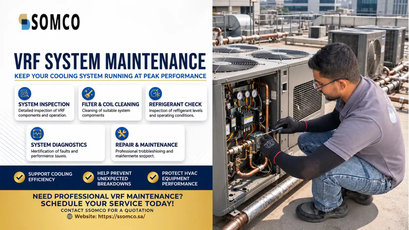
VRF and VRV System Maintenance Guide
Regular maintenance helps identify developing issues and supports reliable system operation.
Maintenance activities should follow manufacturer guidance and be adjusted according to equipment type, operating hours, building environment, and maintenance history.
1. Indoor Unit Filter Cleaning
Air filters collect dust and airborne particles during normal operation.
Maintenance may include:
- Inspecting filter condition.
- Cleaning or replacing filters as required.
- Checking filter installation.
- Inspecting the return-air area.
- Reviewing airflow restrictions.
Filter cleaning frequency should reflect the manufacturer’s instructions and actual site conditions.
2. Indoor Coil Inspection and Cleaning
Indoor heat exchangers should be inspected for dirt accumulation and airflow restrictions.
Cleaning methods should be appropriate for the equipment and should not damage fins, coatings, sensors, or nearby electrical components.
3. Outdoor Unit Inspection
Outdoor units should be inspected to confirm suitable airflow and equipment condition.
Checks may include:
- Outdoor coil condition.
- Fan operation.
- Airflow obstruction.
- Visible damage.
- Unusual noise or vibration.
- Electrical enclosure condition.
- Equipment support and mounting.
The surrounding area should remain suitable for the equipment’s required airflow and maintenance access.
4. Condensate Drainage Inspection
Indoor unit drainage systems should be checked for blockage, leakage, and poor drainage.
Maintenance may include:
- Drain pan inspection.
- Drain line inspection.
- Checking for water accumulation.
- Reviewing drain connections.
- Checking pump operation where fitted.
5. Electrical and Communication Checks
Electrical and communication components should be inspected by qualified personnel using suitable safety procedures.
Checks may include:
- Electrical connections.
- Control wiring.
- Communication terminals.
- Protective devices.
- Controller operation.
- Sensor condition.
- Recorded faults and alarms.
6. Refrigerant Circuit Inspection
The refrigerant circuit should be reviewed when system performance or fault history indicates a potential issue.
Maintenance may include:
- Inspection for visible signs of leakage.
- Reviewing relevant operating parameters.
- Checking system fault history.
- Investigating abnormal operating conditions.
- Carrying out approved leak detection procedures where necessary.
Refrigerant should not simply be added whenever cooling performance decreases. The cause of the problem should be diagnosed first.
7. Controller and System Operation Review
Controllers should be checked to ensure the system operates according to the building’s requirements.
This may include reviewing:
- Temperature settings.
- Operating modes.
- Scheduling.
- Zone controls.
- Error messages.
- Central controller communication.
- BMS integration where applicable.
8. Maintenance Reporting
After planned maintenance, the contractor should provide a report documenting:
- Equipment identification.
- Inspection activities.
- Work completed.
- Equipment condition.
- Observed faults.
- Corrective recommendations.
- Outstanding requirements.
These reports help building managers monitor equipment history and plan future maintenance.
Example VRF/VRV Maintenance Schedule
The following is an illustrative maintenance framework. It is not a universal manufacturer schedule.
Maintenance activity | Example planning frequency |
Indoor filter inspection | Monthly or according to site conditions |
Indoor unit visual inspection | During scheduled service visits |
Condensate drainage inspection | During scheduled maintenance |
Outdoor unit visual inspection | During scheduled maintenance |
Coil condition inspection | According to operating conditions |
Electrical and communication checks | At planned service intervals |
System fault history review | During scheduled maintenance |
Refrigerant circuit inspection | When indicated by inspection or operating conditions |
Overall equipment condition review | At planned intervals |
The actual schedule should be established using manufacturer instructions, operating conditions, equipment history, and the building’s maintenance programme.
Common VRF and VRV Problems and Their Possible Causes
Like other HVAC systems, VRF and VRV equipment can develop operating problems.
The correct diagnosis depends on the equipment model, fault history, installation configuration, and actual operating conditions.
Common problem | Possible causes | Recommended action |
Insufficient cooling | Restricted filters, dirty coils, airflow problems, control issues or refrigerant circuit faults | Inspect the indoor and outdoor units and diagnose the cause |
Uneven room temperatures | Air distribution issues, sensor problems or incorrect settings | Review zone controls and airflow |
Water leakage | Blocked drainage, poor drain installation or pump problems | Inspect the drain pan, drain line and pump |
Communication errors | Wiring issues, connection faults or configuration problems | Check communication wiring and manufacturer diagnostics |
Frequent system shutdown | Protective alarms, abnormal operating conditions or equipment faults | Review error history and perform system diagnostics |
Unusual noise | Fan, vibration, mounting or mechanical issues | Inspect the affected unit |
Poor airflow | Dirty filters, fan problems or restricted air passages | Inspect filters, fans and airflow paths |
Refrigerant-related alarms | Possible leakage, sensor faults or other circuit issues | Carry out manufacturer-approved diagnostics |
These causes are examples, not confirmed diagnoses. A qualified technician should inspect the system before recommending repairs or refrigerant-related work.
VRF and VRV Maintenance Mistakes to Avoid
Incorrect maintenance practices can affect system performance and may create unnecessary repair costs.
Businesses and facility managers should avoid the following mistakes.
1. Ignoring Manufacturer Maintenance Procedures
Different manufacturers and equipment models may have different inspection and service requirements.
Better approach: Follow the correct installation, operation, and maintenance documentation for the installed model.
2. Neglecting Air Filters
Restricted filters can affect airflow and indoor unit performance.
Better approach: Inspect and clean or replace filters according to the equipment instructions and site conditions.
3. Ignoring Condensate Drainage
Blocked or poorly maintained drainage can cause water leakage.
Better approach: Include drain pan and condensate line inspections in the maintenance programme.
4. Adding Refrigerant Without Diagnosing the Problem
Low refrigerant levels may indicate a leak or another system issue.
Better approach: Investigate the cause, follow approved leak detection procedures, and carry out repairs before restoring the specified charge.
5. Using Unqualified Personnel
VRF/VRV systems can require specialist knowledge of refrigerant circuits, electronics, controls, and manufacturer-specific diagnostics.
Better approach: Use appropriately trained and authorised technicians.
6. Skipping Commissioning Documentation
Incomplete commissioning records can make future maintenance and troubleshooting more difficult.
Better approach: Retain approved installation drawings, test records, system settings, and handover information.
7. Ignoring Recurring Error Codes
Repeated faults may indicate an unresolved underlying issue.
Better approach: Review fault history and investigate recurring problems rather than repeatedly resetting the equipment without diagnosis.
VRF and VRV Systems vs Traditional Split AC Systems
VRF/VRV and conventional split air-conditioning systems have different applications and design requirements.
Feature | VRF/VRV systems | Conventional split AC systems |
System arrangement | Multiple indoor units connected through a designed refrigerant network | Usually one indoor unit connected to one outdoor unit |
Zone control | Individual control across compatible indoor units | Usually controlled by each individual system |
System complexity | More complex piping, controls and commissioning | Generally simpler system arrangement |
Application | Multi-zone commercial and larger residential projects | Individual rooms and smaller areas |
Installation planning | Requires detailed system design and manufacturer calculations | Requires equipment selection and individual installation planning |
Maintenance | Requires system-level and unit-level checks | Generally maintained at individual system level |
Expansion | Subject to approved system capacity and design limits | Usually requires separate or compatible additional systems |
The most appropriate system depends on the building’s cooling requirements, layout, operating conditions, available infrastructure, and budget.
How to Choose a VRF/VRV Installation and Maintenance Contractor
Selecting the right contractor is essential for successful installation and ongoing system performance.
Consider the following factors before appointing a service provider.
1. Manufacturer-Specific Experience
Ask whether the contractor has experience with the specific VRF/VRV manufacturer and equipment model installed at your property.
2. Installation and Design Capability
For new installations, review the contractor’s ability to coordinate cooling load calculations, equipment selection, refrigerant piping, electrical requirements, and system documentation.
3. Qualified Technical Personnel
Confirm that technicians have suitable training and experience for VRF/VRV installation, commissioning, and maintenance.
4. Proper Installation and Commissioning Procedures
Ask how the contractor manages refrigerant piping tests, evacuation, refrigerant charging, field settings, system test runs, and commissioning records.
5. Maintenance Scope
Review whether the maintenance agreement includes indoor units, outdoor units, drainage, controls, electrical inspections, system diagnostics, and reporting.
6. Safety and Refrigerant Handling
Confirm that the contractor follows suitable safety procedures and applicable refrigerant handling requirements.
7. Documentation and Reporting
A suitable contractor should provide service reports, installation records, commissioning documentation, and recommendations according to the agreed scope.
8. Clear Quotation and Contract Terms
Check equipment coverage, maintenance frequency, labour, parts, exclusions, response arrangements, and contract duration.
Why Consider SSOMCO for VRF and VRV System Services?
Saudi Specialized Operations & Maintenance Company (SSOMCO) provides HVAC and maintenance-related solutions for commercial and business environments, including VRF system installation and maintenance services.
Businesses planning a new VRF/VRV installation or looking for maintenance support should first assess their building requirements and existing equipment.
When discussing your project, prepare the following information:
- Building type and location.
- Total number of indoor units.
- Outdoor unit details.
- Manufacturer and model information.
- Existing system drawings, if available.
- Installation or maintenance requirements.
- Current operating problems.
- Preferred maintenance frequency.
- Project scope and expected timeline.
This information helps establish a clearer starting point for discussing the appropriate HVAC service requirements.
Planning a VRF/VRV installation or need maintenance support? Contact SSOMCO to discuss your commercial HVAC requirements and request a quotation.
Frequently Asked Questions
VRF stands for Variable Refrigerant Flow, while VRV stands for Variable Refrigerant Volume. Both describe similar variable-refrigerant air-conditioning technology. VRV is Daikin's branded term, while VRF is commonly used as the general industry term.
They use an outdoor unit or system arrangement connected to multiple indoor units through refrigerant piping. The system adjusts refrigerant flow and compressor operation according to the cooling or heating requirements of connected zones.
Yes. They may be suitable for offices, hotels, retail properties, restaurants, and other multi-zone buildings, depending on the cooling requirements and system design.
Main components include outdoor units, indoor units, refrigerant piping, branch joints or selector units where applicable, control systems, electrical connections, and condensate drainage arrangements.
A heat-pump system generally operates in either cooling or heating mode across its connected arrangement. A compatible heat-recovery system can support simultaneous heating and cooling in different zones.
Installation time depends on building size, equipment capacity, number of indoor units, piping complexity, site access, electrical work, and commissioning requirements. A realistic schedule can be established after a site assessment and approved design.
Maintenance frequency depends on manufacturer recommendations, operating hours, environmental conditions, equipment type, and system history. A maintenance programme should be prepared for the specific installation.
Maintenance may include filter cleaning, coil inspection, condensate drainage checks, outdoor unit inspection, electrical and communication checks, controller review, and system diagnostics.
Possible causes include dirty filters, restricted airflow, coil condition, incorrect settings, sensor problems, communication faults, or refrigerant circuit issues. A qualified technician should diagnose the actual cause.
Some heat-recovery VRF/VRV configurations can provide simultaneous heating and cooling to different zones. Standard heat-pump arrangements generally do not provide this capability across the connected system.
Yes. Installation, commissioning, and advanced maintenance should be performed by appropriately trained and authorised personnel who understand the manufacturer's equipment and procedures.
Not automatically. Refrigerant-related work, spare parts, labour, and major repairs depend on the written maintenance agreement. Businesses should confirm all inclusions and exclusions before signing.
Conclusion
VRF and VRV systems provide flexible air-conditioning solutions for commercial buildings that require multiple temperature-controlled zones. Their performance depends on correct system design, suitable equipment selection, professional installation, manufacturer-compliant commissioning, and regular maintenance.
From refrigerant piping and electrical connections to indoor unit cleaning, outdoor equipment inspections, and system diagnostics, every stage requires appropriate technical knowledge.
For building owners and facility managers, selecting a qualified HVAC contractor and maintaining accurate equipment records can help support reliable system operation and better maintenance planning.
Need professional VRF/VRV installation or maintenance services? Contact SSOMCO to discuss your building’s HVAC requirements and request a quotation.

Professional HVAC Service: Ensuring Comfort Year-Round - Best Air Duct And Kitchen Hood Cleaning Service Provider In KSA
November 10, 2026 10:46 am[…] VRF and VRV system maintenance. […]